HDD PCB, ROM and Adaptive Data Recovery
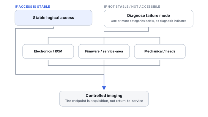
A donor PCB has to do more than fit the drive electrically — it has to carry, or be made to carry, the drive-specific ROM and adaptive information the patient drive needs to initialize its heads, service area and user data. A matching part number is not the same thing as a matching drive personality, and the aim of the work is stable enough access for controlled imaging, not a repaired drive.
- A board part-number match is only one selection criterion; it does not guarantee electrical, firmware or adaptive compatibility.
- Drive-specific data can be split between the board’s ROM and the service area, so a ROM dump is not automatically the drive’s complete adaptive set.
- Whether the original ROM can be used depends on the design and damage: a readable external chip, ROM inside the controller, a damaged chip, or a doubtful read.
- Preserve the ROM by the safest available means; that is not a reason to keep powering a board suspected of a short or internal damage.
- Spin-up, model identification or a few readable sectors do not prove stability; the goal is controlled imaging, not returning the drive to service.
What is actually on the PCB
An HDD’s circuit board carries power regulation, the motor/controller circuitry, the interface PHY, and — on many drives — ROM or NVRAM holding firmware and drive-specific configuration. Treating “PCB,” “ROM” and “firmware” as interchangeable terms causes real confusion here, because they refer to related but distinct things, and a repair to one does not automatically fix the others.
Adaptive data can be unique to the individual drive
Modern HDDs can store calibration and adaptive information tied to the specific heads, preamplifier and channel installed on that unit — manufacturing-specific parameters, not generic firmware. That is why a visually identical donor board can fail to initialize a patient’s head stack assembly correctly: the donor carries its own donor-specific adaptive data, not the patient’s.
Drive-specific data is split between ROM and the service area
The ROM on the board is not the only place drive-specific information lives. Part of the firmware and of the unit’s own parameters is written in the service area on the platters, and the division between board and platters differs by vendor, family and firmware generation. On some designs the ROM holds the parameters the drive needs before it can read its own service area at all; on others more of the unit-specific state sits in service-area modules. HDD Firmware, Service Area and Translator Recovery explains that side of the split.
Two consequences follow. A ROM dump, even a complete and verified one, is a copy of what was on that chip; it should not be described as the drive’s complete set of adaptives. And a damaged service area cannot be repaired by board work alone, just as a healthy service area does not compensate for ROM content that does not belong to the patient.
Is the original ROM still usable?
“Transfer the ROM” assumes the original ROM content can still be obtained intact. Several different situations hide behind that assumption, and which ones are possible depends on the board design.
Scroll horizontally to see the full table →
| State of the original ROM | What it may allow | What it does not establish |
|---|---|---|
| Separate external chip, readable | Reading the content with a programmer even when the rest of the board is damaged, or moving the content or chip to a compatible donor board on designs that use this layout | That the donor board is otherwise compatible, or that the read is complete until it has been verified |
| ROM integrated into the controller (MCU) | There is no separate chip to transfer. Any supported route for obtaining or restoring the original ROM must be established for that family and damage state | That a route exists for that family at all |
| Chip or controller damaged | Possibly a reconstruction from other sources on families where one is supported; sometimes nothing | That the original content can always be recovered; the service area is not a guaranteed backup of the ROM |
| Read obtained but incomplete or doubtful | A starting point for comparison with repeated reads and with the structure expected for that family | That the content is correct; a dump with errors written to a donor can add a new fault on top of the original one |
Vendor-specific examples show how much this varies. Acelab’s PC-3000 blog, for instance, describes reading an external ROM chip with a programmer when PCB damage prevents reading it through the tool, using a Seagate drive whose donor PCB cannot be used without the original ROM data. These are one tool’s procedures for particular families, not a general rule that a chip can be moved on every model or that ROM can always be recovered from the service area.
Four different things can be meant by “PCB swap”
Repairing the original PCB keeps the patient’s ROM and adaptive data associated with the patient HDA and introduces the fewest new variables, which is why it’s preferred when the damage is contained and repairable. A compatible donor PCB with the original ROM chip transferred across is possible on designs where the drive-specific data sits on a separate, removable flash chip. Where the ROM itself is damaged or integrated into the controller, the data may need to be reconstructed or reprogrammed onto a donor, on families where a route for that exists. And a donor board is sometimes used purely diagnostically by a lab — to check whether the original PCB, spindle circuitry or interface PHY responds at all — without any expectation that the donor’s own adaptive data will let the drive work normally. That diagnostic use is a controlled step with known risks, not a shortcut to try at home: powering a patient HDA with an unmatched donor board or donor ROM content can add stress to heads and media that are already in question.
A part-number match is only one criterion
A matching board number narrows the search; it does not settle compatibility. Boards with the same printed number can differ in revision, controller, motor-driver components or firmware, and two drives with the same model name can belong to different families. What has to match, and what can be adapted, is specific to the family and revision. HDD Donor Parts and Compatibility covers the matching parameters themselves.
A part-number match is one selection criterion. It does not guarantee electrical, firmware or adaptive compatibility, and it does not tell you whether the donor’s ROM and adaptive data will let it operate the patient’s specific head stack — that is a separate question, and how to check it depends on the family and revision.
A donor board that clicks doesn’t prove the heads are bad
If a donor PCB carries adaptive data that doesn’t match the patient HDA, the drive can fail to access its service area, fail calibration, seek repeatedly, and click — the same symptom a genuine head failure produces. Clicking after an unmatched PCB swap can be a compatibility problem between donor electronics and patient mechanics, not proof that the heads themselves are damaged. Reaching for a head-replacement plan at that point, before ruling out the adaptive-data mismatch, can mean replacing parts that were never actually broken. When head work really is indicated, Cleanroom Head Replacement and Donor Matching covers it.
Training scenario: a same-number donor board, and the drive now clicks
After a power event the drive was not detected. A board with the same printed number was fitted; the drive now spins up and clicks repeatedly. The original board has not been touched since.
The clicking is consistent with donor ROM or adaptive data that does not belong to the patient, and also with heads or a preamplifier damaged by the same electrical event. On its own it does not distinguish between them.
Stop powering the drive with the donor board, keep the original board unaltered and labelled, and have the ROM state, the board damage and the HDA assessed before any further power-on.
If the original ROM content cannot be read or reconstructed for that family, a matching board alone may not be enough, and each extra power-on with mismatched electronics can add risk to the heads and media.
Electrical damage can reach past the board itself
An electrical event doesn’t necessarily stop at the PCB. Overvoltage can propagate through the read channel into the preamplifier that sits inside the sealed head-disk assembly near the heads themselves. When that happens, a correctly matched donor PCB can still fail, the drive can still click, and the heads may genuinely need replacement — the original event, not a misdiagnosis, damaged more than one layer.
Preserve ROM and adaptive data safely
Because adaptive and service-area data are often the hardest part of a case to reconstruct once lost, securing whatever ROM or adaptive information is still accessible — before firmware experiments, board swaps or writes of any kind — is standard professional practice. It preserves the option to recover from a mistake that a more improvised approach would close off permanently.
“Before any step” means by the safest means available for that board, not “power it up and read it now”. A board suspected of a short circuit or internal electrical damage should not be powered repeatedly just to attempt a read; depending on the design, the content may be reachable without powering the damaged board at all, and the damage itself has to be assessed first. Nor is there a universal mandatory order of PCB, then firmware, then heads: diagnosis decides which layers are involved, and several can be damaged by the same event.
Keep a record of every intervention
Board and ROM work mixes parts and data from more than one drive, so professional handling keeps them traceable:
- Label patient and donor parts — boards, chips, HDAs — so it is always clear which board and which ROM content belong to which drive.
- Save the original dump before anything is written, and verify the read, for example by comparing repeated reads and checking that the content has the structure expected for that family.
- Work on a copy of the dump; keep the original file unchanged.
- Keep a change log: what was read, written, moved or adapted, onto which part, when, and with what result.
- Keep the original board, even when it seems beyond repair.
A hash of the saved dump confirms later that the file has not changed since it was hashed. It does not prove the dump was read correctly or that it is complete. How original images and working copies are kept apart in general is covered in Recovery Copies.
The goal is stable access for imaging
Board and ROM work is aimed at one thing: making the drive stable enough to image under control. A drive that spins up, reports its model or serial number, or returns a few sectors after a board repair or swap has not yet shown that it is stable, and the heads, media and service area can still fail during a long read. None of these signs means the drive is fit for further use either; it remains a source to be copied, not a disk to return to service. The imaging itself is covered in How to Image a Failing Drive Safely and Imaging Bad Sectors and Unstable HDDs.
Technical references: Acelab PC-3000 Express product page — a professional tool that reads and writes flash ROM, diagnoses the PCB, allows the board to be repaired or substituted from a donor, and checks service-area modules separately · PC-3000 Support Blog: How to read ROM via programmer device — reading an external ROM chip with a programmer when PCB damage prevents reading it through the tool; a Seagate example whose donor PCB cannot be used without the original ROM data · PC-3000 Support Blog: Glossary — ROM holding unit-specific microcode, including parameters that let the drive read its service area, and adaptive data needing to follow a PCB replacement. All three are one tool vendor’s product documentation for particular products and drive families; they show what that tool supports, not a universal procedure or a compatibility guarantee for other models.
Related: HDD Firmware, Service Area and Translator Recovery · Cleanroom Head Replacement and Donor Matching · HDD Heads, Platters and Mechanical Failure · HDD Donor Parts and Compatibility · Recovery Copies · Power Surge or Electrical Failure · Drive Not Detected or Keeps Disappearing