Understanding Storage Layers Before Recovery
A storage system rarely consists of “a disk and some files.” Modern data may pass through several mapping layers before an application sees it. Recovery becomes much more reliable when those layers are identified first and reconstructed from the bottom up instead of scanning the wrong representation as if it were a flat disk.
- Data often passes through several mapping layers: disk, RAID, pool, encryption, partitions, file system, virtual disk.
- The same sectors mean different things at different layers.
- Start with the lowest damaged or uncertain layer and reconstruct upward.
- Scanning the wrong layer can mix unrelated extents or miss mappings entirely.
- Draw the stack before scanning: mark which layers are confirmed, uncertain or failed.
The same sectors can mean different things at different layers
A physical disk exposes sectors. A RAID controller may combine sectors from several disks into one virtual address space. A storage pool can remap that space again; encryption transforms its contents; a partition defines a region; a file system maps files to extents; a virtual disk can contain another partition table and another file system. Each layer interprets the output of the layer below it.
This is why seeing recognizable bytes is not enough. Data can be physically present while remaining meaningless until the mapping that gives those bytes their logical addresses is restored.
A practical storage stack
A layered system is built from whichever mappings an administrator actually chose, in whatever order they were applied — there is no single sequence every system follows. The chain below is a common pattern on consumer and NAS systems:
Physical device(s) → RAID/storage mapping → pool or volume manager → encryption → partition/container → file system → virtual disk or database → application data
Two equally normal variants:
- Single encrypted disk: physical disk → partition → encrypted volume → file system — encryption sits above the partition here, not below it.
- NAS/SAN array: member disks → RAID → LVM or a storage pool → file system → virtual disk → guest-OS layers, if any.
LVM, ZFS and Btrfs don't all insert the same layers the same way: ZFS and Btrfs typically fold pooling, volume management and the file system into one subsystem rather than stacking them as separate mappings the way LVM-on-RAID does.
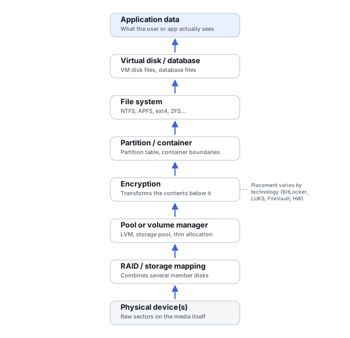
Not every system contains every layer, and some layers can appear more than once. A virtual machine, for example, may live on a host file system while its virtual disk contains its own partition table, encryption and guest file system. A NAS may place a file system on top of RAID and LVM, while also exposing snapshots or iSCSI LUNs above it.
Why recovery usually proceeds from lower layers upward
If a RAID layout is wrong, the file system assembled from it may contain convincing directory structures mixed with corrupt data. If an encrypted layer is skipped, scanning ciphertext for file signatures is generally meaningless. If a thin-provisioning map is missing, physical offsets do not necessarily correspond to logical offsets in the LUN.
The useful rule is not “always recover the lowest possible layer.” It is: start with the lowest layer that is damaged or uncertain, preserve it, and reconstruct enough of it to obtain a trustworthy representation of the next layer.
A concrete sequence shows what that means in practice. Imaging a single member of a striped RAID layout in isolation yields that disk's own sectors — readable fragments, but not a coherent address space, since striping splits data across members. Correctly identifying stripe size, member order and parity role and assembling the members into a virtual array produces an address space that behaves like a single logical block device, the way Linux software RAID represents it once assembled. A successful assembly is suggested by the members' own metadata agreeing on geometry and by the resulting space yielding a consistent partition table — not merely by the assembly tool finishing without an error. Only once that address space is trustworthy does checking the file system and individual files become meaningful: a directory listing that resolves correctly is a reasonable sign the assembly is close, but it does not confirm every file's content, and one file opening correctly does not confirm the rest of the volume is undamaged.
What to identify before scanning
- Representation type. A physical device, member disk, disk image, logical LUN, virtual disk, exported volume, or something else?
- Identity and capacity. Serial numbers, volume or array identifiers, and the capacity each layer should report — an unexpected capacity can invalidate every higher-level offset.
- Available mappings. Is there RAID, pooling, thin provisioning or virtualization underneath, and which mapping turns the lower layer into the address space the next layer expects? Member disks should not automatically be scanned as independent file systems.
- Where encryption and keys live. Which layer is encrypted, and where the keys, metadata and credentials needed to open it are kept.
- Dependent components. Other members, pool metadata, a parent snapshot, or a host file system this layer cannot be interpreted without.
- Access mode. Whether the source can be read directly, only through a controller or API, or only after some assembly or decryption step.
- Confirmed vs. uncertain. Which layer still parses correctly — a valid partition table does not prove the file system is healthy, and a valid file system does not prove application data is consistent.
This inventory can be built by observation: listing identifiers, capacities and reported states does not require initializing, repairing or writing to anything in the stack.
Choosing the correct recovery source
The original physical device is not always the object that recovery software should scan. After safe acquisition, the correct source might be a disk image, a reconstructed virtual RAID, an assembled storage pool, a decrypted volume, a virtual disk extracted from a host file system or a point-in-time snapshot.
Scanning too low can discard mappings and mix unrelated extents. Scanning too high can hide the layer that actually failed. When possible, keep the lower-level acquisitions so that the reconstruction can be revised without returning to the original media.
A copy taken at one layer does not necessarily carry everything the layers below or around it hold. A logical image taken above a storage pool preserves the visible blocks of that representation, but not the pool's own hidden allocation mappings, nor any other volumes or snapshots sharing the same pool. Imaging an encrypted source copies ciphertext; it does not create or recover the keys needed to read it. Exporting files through a mounted file system captures those files, not a full image of the volume they came from — free space, deleted-but-recoverable data and lower-layer metadata are generally lost in that step. No single level is universally the "best" one to copy; which copy is sufficient depends on what the recovery still needs from the layers it leaves behind.
Scroll horizontally to see the full table →
| Representation copied | Contains | Does not preserve |
|---|---|---|
| Raw physical device/member | The logical sectors actually reachable and read through the chosen interface during acquisition | The logical address space RAID or pooling would assemble from multiple members; bad or unread sectors (track these separately, don't assume they're included); HDD hidden/service areas, SSD overprovisioning or earlier NAND mappings — none of these become accessible just because the image is called “physical” |
| Whole assembled RAID/pool array (block image) | Whatever the acquisition actually captured from the reconstructed address space — which can include pool metadata and more than one volume together | Completeness beyond what the acquisition covered; the word “assembled” doesn't by itself guarantee every volume or all pool metadata was captured — check the acquisition's own scope |
| Individual exported pool volume/LUN | That specific volume or LUN's own logical address space | Other volumes or snapshots sharing the same pool; hidden pool allocation metadata |
| Encrypted volume (ciphertext) | The encrypted bytes as stored | The keys needed to read them — imaging does not create or recover key material |
| Decrypted logical block image | The logical blocks returned by the decrypted volume, including available unallocated space | Bytes already overwritten or TRIMmed before decryption; other lower-layer mappings, other volumes or snapshots sharing the same underlying storage |
| File-level export from a file system | Selected accessible files and whatever metadata the specific export method actually keeps | The full block address space, unallocated space, and most file-system metadata that isn't attached to an exported file |
Examples where the layer changes the answer
- RAID: scanning one member of a striped layout can produce fragments, not the logical array address space — but a RAID1 member can hold a complete mirrored logical copy on its own; whether that's actually usable still depends on confirming offsets, any wrapper metadata, and how current that particular member is.
- NAS: vendor partitions may be visible on each disk while user data belongs to a RAID/LVM/Btrfs/ZFS layer above them.
- SAN: physical pool data, a thin LUN and the host file system are different recovery sources.
- Virtual machines: host storage can be intact while a snapshot chain is broken, or the VM container can be intact while the guest file system is damaged.
- Encryption: file-system metadata may only become interpretable after the encryption layer is correctly opened.
When raw recovery is appropriate
Raw carving deliberately ignores much of this structure. That can be useful when higher-level metadata is destroyed, but it should normally be a fallback rather than the first way to flatten a layered system. Carving cannot recreate RAID geometry, encryption keys, thin-allocation maps, filenames or fragmented-file extent maps that were never reconstructed.
A safer decision rule
Before scanning a complex source, draw the storage stack you believe exists. Mark which layers are confirmed, which are uncertain and which have failed. Acquire unstable physical sources first; then reconstruct the lowest uncertain mapping and validate it before moving upward.
Technical references: Linux kernel: software RAID (md) — members as one logical device · Linux kernel: device-mapper thin provisioning — thin pools
Related: Data Recovery Workflow · What a Disk Image Actually Preserves · Recovery Copies: Masters, Working Copies and Scope · RAID Reconstruction Basics · Sparse, Thin-Provisioned and Virtual Storage · Validating Recovered Data · Metadata vs. Raw Recovery · Wrong Drive Capacity · Virtual Disk Corruption · Hex Editors & Disk Structure Viewers · Drive Cages & RAID Enclosures · USB/SATA & NVMe Adapters.